|
|
|
|
|
|
|
| |
|
|
 |
|
 |
|
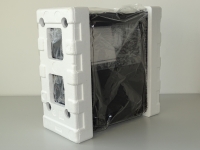
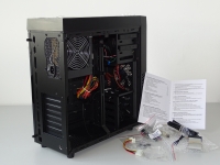
1.
Unpack
BlackBOX
|
|
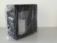
2.
Remove the plastic bag
|
| |
|
|
 |
|
 |
|
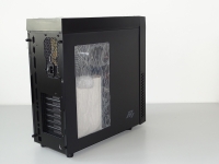
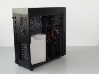
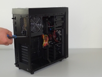
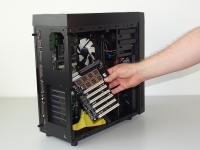
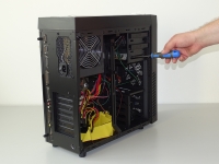
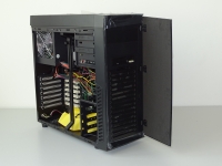
3.
Unscrew
two bolts and remove right side wall
|
|
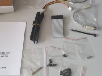
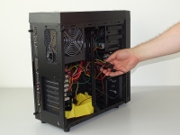
4.
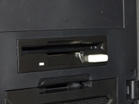
Pull
out the bag with BlackBOX
accessories
|
| |
|
|
 |
|
 |
|
5.
Read
manual
|
|
6.
Check
BlackBOX accessories
|
| |
|
|
 |
|
 |
|
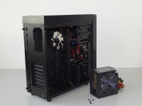
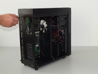
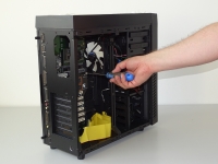
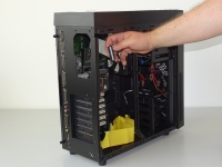
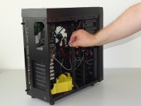
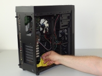
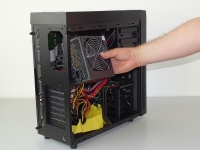
7.
Unscrew
4 power supply bolts
|
|
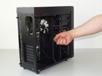
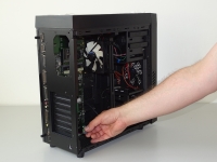
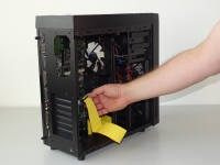
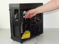
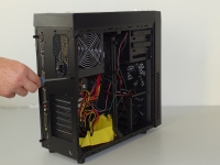
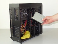
8.
Remove
the power supply
|
| |
|
|
 |
|
 |
|
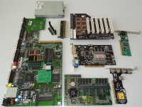
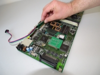
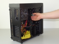
9.Prepare
your Amiga items for installation.
|
|
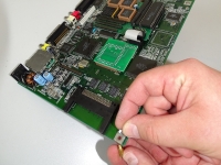
10.
Install
the stand off
|
| |
|
|
 |
|
 |
|
11.
Stand
off properly installed
|
|
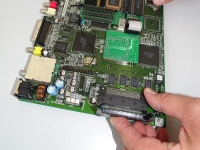
12.
Install
PCMCIA right angle adapter (if you have it)
|
| |
|
|
 |
|
 |
|
13.
PCMCIA
adapter properly installed
|
|
14.
Fit
the Mediator passthrough
|
| |
|
|
 |
|
 |
|
15.
Mediator
passthrough installed
|
|
16.
Install
your turbo card
|
| |
|
|
 |
|
 |
|
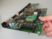
17.
Install
A1200 PC-KEY interface (enclosed in a BlackBOX accessories bag)
|
|
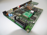
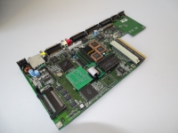
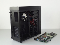
18.
A1200
motherboard prepared for installation in the BlackBOX
|
| |
|
|
 |
|
 |
|
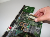
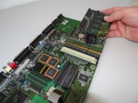
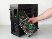
19.
Fit
A1200 motherboard into the tower
|
|
20.
Put
motherboard so its ports are placed in appropriate openings
|
| |
|
|
 |
|
 |
|
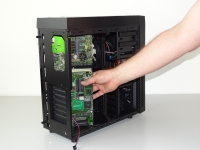
21.
Slightly
screw using enclosed hexagon socket wrench twelve sleeves
unscrewed earlier
|
|
22.
Screw
down the Amiga board to the side wall using Mediator sleeve,
next screw tight twelve back sleeves
|
| |
|
|
 |
|
 |
|
23.
Connect
PC-KEY 1200 interface ribbon to the DIN socket
|
|
24.
Install
FastATA ribbon(s)
|
| |
|
|
 |
|
 |
|
25.
Install
Mediator busboard
|
|
26.
Screw
Mediator to its sleeve
|
| |
|
|
 |
|
 |
|
27.
Install
FDD ribbon (enclosed in a BlackBOX accessories bag)
|
|
28.
Plug
BlackBOX LED adapter cable to the A1200 LED pins
|
| |
|
|
 |
|
 |
|
29.
Connect
BlackBOX POWER switch cable to the Mediator Power SW pins
|
|
30.
Connect
BlackBOX RESET cable to the RESET SW on GAYLE board (if you
have it)
|
| |
|
|
 |
|
 |
|
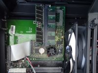
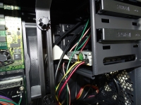
31.
Inside
view of installed turbo card
|
|
32.
Connect
ATX power plug to the Mediator ATX power socket
|
| |
|
|
 |
|
 |
|
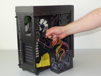
33.
Install
the BlackBOX power supply
|
|
34.
Screw
back the power supply
|
| |
|
|
 |
|
 |
|
35.
Insert
the original A1200 floppy drive in to the 3,5" bay
|
|
36.
Adjust FDD position
|
| |
|
|
 |
|
 |
|
37.
Adjust
FDD position
|
|
38.
Adjust
FDD position
|
| |
|
|
 |
|
 |
|
39.
Screw
the FDD (from both side)
|
|
40.
Connect
the FDD ribbon and the FDD power to the floppy drive
|
| |
|
|
 |
|
 |
|
41.
Connect
tower fan controll adapter to the power supply
|
|
42.
Install
HDDs, CD drive and PCI cards...
|
| |
|
|
|
|